Bought a sign that was controlled with a IR remote and decided to replace with a pi for wifi control but haven’t figured out the correct settings.
Setup:
Raspberry Pi 3 with 64 bit debian bookworm
Adafruit bonnet unmodified
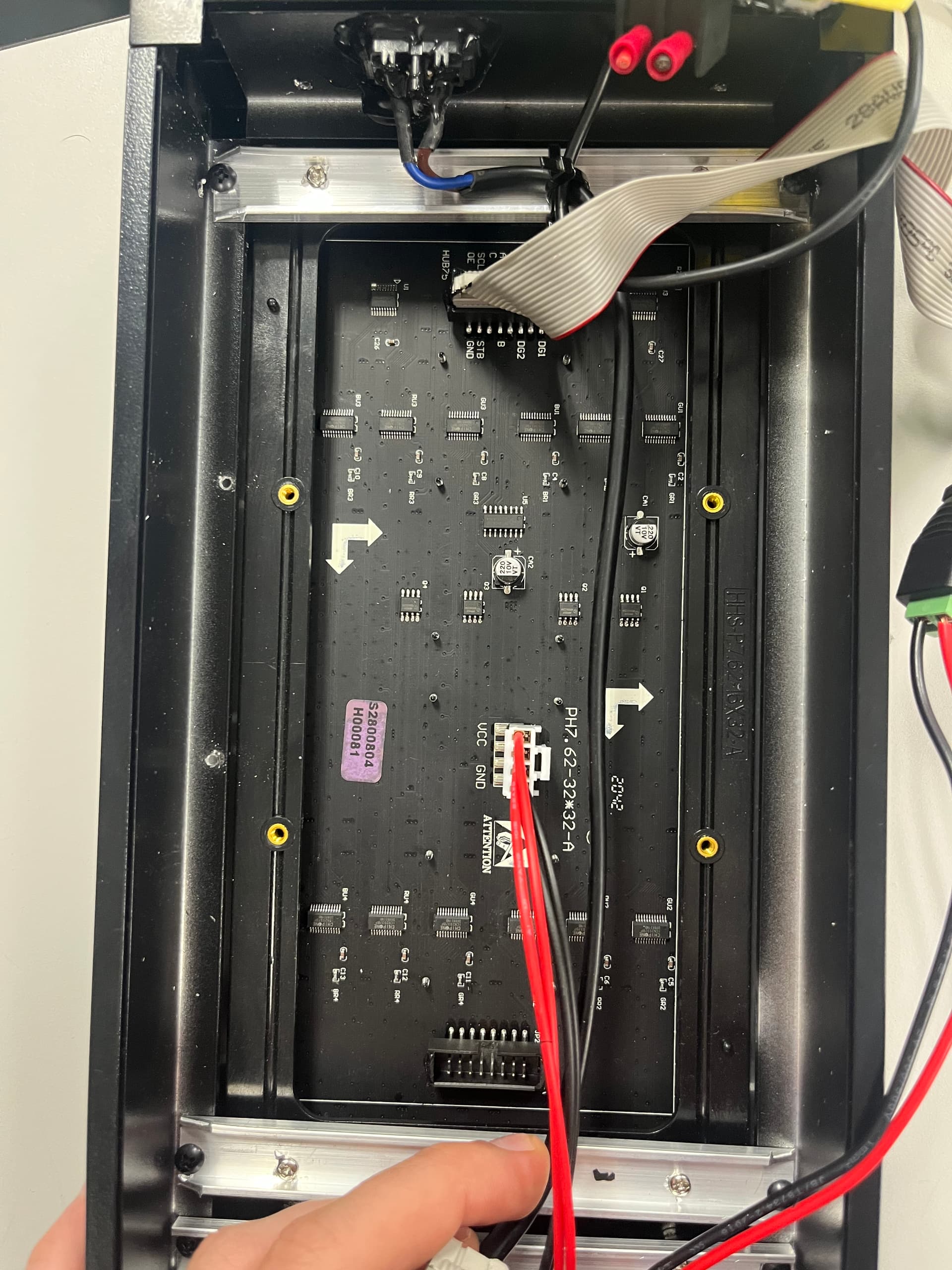
P7.62-32*32-A panel with
Chipone ICN2037BP led drivers
SunMoon SM74HC138D multiplexers
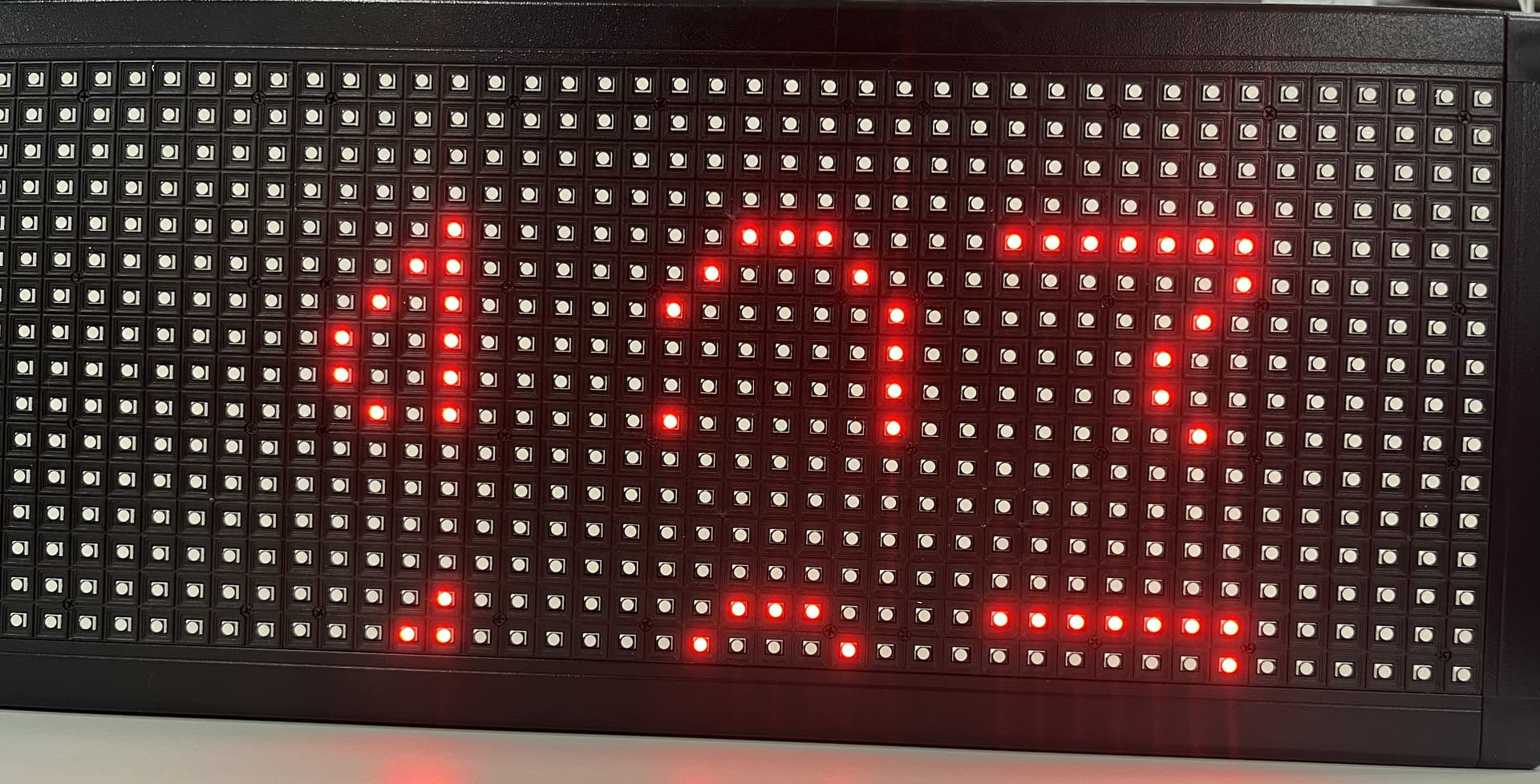
Best results so far have been with sudo ./text-scroller -f ../fonts/9x18.bdf --led-rows=16 --led-cols=32 --led-parallel=1 --led-slowdown-gpio=3 --led-gpio-mapping=adafruit-hat --led-scan-mode=1 --led-chain=1 --led-row-addr-type=0 -C255,0,0 -s0 “123” --led-multiplexing=0
This results in a display that seems to repeat after 8 pixel rows, columns don’t look bad. Reading the github and discourse, I looked at the HUB75 and only see ABC address lines so am assuming this is a 16(8x2) x 32 panel because I count 16 vertical leds and 32 horizontal per board (there’s two boards chained together but just testing 1 until it works). A bit contradicting between what the silkscreen says versus how the board is actually laid out. Have wrote some bash scripts that loop through all the multiplexing and address types but with no joy. Any ideas?