I did already write that it works. And it’s the same as @graybushused.
Or what do you mean by review? Please read my comments more carefully: I pointed out that I would like to add more pics was so far preventing from doing so, nor could I change the title of this post. And even though I got an email earlier that I’m “upgraded” here, I still can’t edit the first post of mine here.
Hi,
Quick question on the Matrix-Controller from JoyIT. I’ve also one now - attached to a Raspi3.
I have no problem getting multiple panels daisy-chained in a single row - but I don’t get multiple rows working (parallel rows).
So my goal would be a 3x2 matrix; I do have 64x32 outdoor panels with HUB75E
I’m wondering if the E-Line is my trouble maker - which sits at PIN 10 of the HUB75 Connector. Or if its my configuration.
Because my expectation when adding multiple rows is that the first (working) row would only contain 1/2 or 1/3 of the demo stuff - but the first row is always ok.
Hence I don’t know if I have a config issue - or if its a PIN addressing issue.
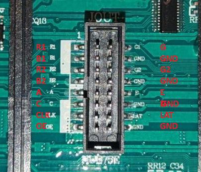
This is the pinout of my Panel
And this my default test routine:
sudo examples-api-use/demo -D 1 examples-api-use/runtext.ppm --led-rows=32 --led-cols=64 --led-chain=2 --led-parallel=2 --led-multiplexing=1 --led-brightness=50
As said, the –led-parallel parameter has no effect; everything else works as expected.
PIN 4 and 8 are connected to GND - as thats the config of my panel.
Any advice is greatly welcome - I’m a bit out of ideas…
Huh, I can’t tell from the “Anleitung DE” on the Reichelt website that you’re supposed to connect both 4 and 8 to GND, but only one of them. Change the jumpers to see if that helps - you can’t damage the panel if you get it wrong, I think.
I only have 64x64 panels so I can’t help you with actual tests, sorry.
I’ve uploaded the ‘input’ side of the P5 Outdoor panel I’m using.
Why do you think by ‘E’ label is actually B? Because of the other ordering (especially regarding GND)? I’ve seen pictures with PIN 10 being B, PIN 12 being D - so is the labeling simply wrong? I’ve actually asked the vendor for a wiring schematic - but nothing so far unfortunately.
What you’ve labed as E in your image is B, whereas E would be the one above B (labeled GND in your case), meaning that the panel has no E. And if it’s a 64x32 panel, then there’s indeed no need or use for E. So there’s nothing wrong with that, I think. Unless you damaged your GPIO on your Pi 3 (that had happened to mine a while back). It’s always good to have another Pi in reserve for testing
What happens if you connect just one panel to each of the 3 connectors? Then use these parms:
There are dufferent types of multiplexer chips on the HUB75 panels - the one of them is a “shift-register” type that uses a three pins only - A B and C. In order to know how to work with the panel, first of all you need to know the type of driver and multiplexer chips.
This does not happen. Most likely, your panel is covered with varnish on the back side, under which the labels on the chips became invisible. But they are there, and can be seen through a magnifying glass or, better, through a microscope with backlighting.
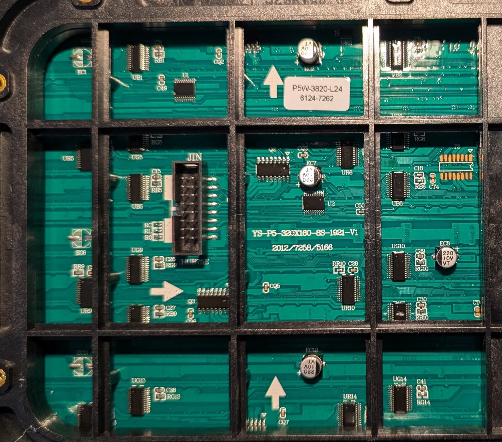
But in this case, most likely, this is not necessary. I see a sticker (highlighted in red) on the panel, the bottom line of which most likely indicates the types of drivers on the matrix:
Most likely this means that the main driver on the panel is FM6124, and the multiplexer is TC7262.
TC7262 is a standard type multiplexer, not a shift-register one, as I assumed above. The number of pins in such a chips depends on the number of scans on the matrix. For 8 scans, ABC pins used, ABCD for 16 scans, and ABCDE for 32s.
Your matrix has a size of 64x32, however, look at the inscription on your panel, which I highlighted in blue. it has only 8 scans - therefore, three ABC pins are enough to control its lines.
Also keep in mind that outdoor panels with a small scan (like yours) usually have a non-standard pixel connection and require adjustment of the “pixel mapping”. More details in the Multiplexing help section .
I’ve understood more about HUB75 and what scans in this regard mean based on your comments compared to x hours of googling and asking AIs (not precise questions given I wasn’t sure on the root cause).
My issue was actually my assumption that demo 1 runs in the center of the ‘screen’; instead it runs in the top row.
After playing with all demo modes I ended with 1 as reference while testing just a single panel. My assumption with 4 panels was that the text is centered vertically - which is not the case. Hence my confusion.
Using demo 0 showed that.
So the panels as shown above work also with the Joy-IT boards (which looks technically like an expensive clone of the hzeller board - but with simple shipping in Germany).