DPI interface is like VGA output, just binary, all 24 bits (8 per color) have own GPIO pins. Clock speed can be set above 100Mhz with about 1khz steps.
I create prof of concept project using just python and DPI output. 100 FPS on rPi 2 for 64x32 LED panel and single core load (calculations done in NumPy).
At the same time, the DPI push data to panel at stable 400hz refresh rate. Theoretical maximum for 8b color is 4khz for single panel and 270hz for 32k pixels data chain mentioned in readme.
@BC_Mike that’s a pretty cool idea.
I’m not sure if @hzeller has time to implement it, but I think you should do a hardware proof of concept and make it easy enough for people to reproduce and do their own.
Also, as your project mentions, the interface might be illegal RF wise? (sigh regulations…), so you’d have to show superior performance to the existing solution, or there will be little incentive to switch.
But even if a hardware version never happens, just the idea is quite cool.
Indeed, though, if you want to do hacking and push to larger limits, it’s probably a good idea to ditch the rPi which was never meant for this, and consider a dedicated board like this one?
I have yet to see an open source solution to rgbpanel driving, and it would be very cool to have one.
Exactly. Python is easier than compile-run-fix typical in C programming. Especially as I deal with rPi hardware and matrix hardware, not with just code modules.
DPI gives me pixel clock but i have issues using it. The clock have constant frequency and can’t be switched off. Synchronization signal (DPI) comes too late and the clock (DPI) pushes few black bits to the matrix. To solve this issue i can generate latch signal on data pins (latch early) or generate clock on data pins (stop clock after last pixel pushed into matrix).
I choose second option for easier control of clock polarity (data clocked by rising or falling edge).
To make software generated clock i have to push the same data twice. Each with alternating signal for CLK pin.
10101010 sending this pattern on single pin gives me 4 CLK pulses, but 8 “pixels” have to be send over DPI interface to make it. Hope You understand that. Can’t find other words to describe that better.
Each line of DPI image gives me 240 bits to play with. Longer chain of panels will have longer rows to send all the data.
I grab that number and multiply by brightness setting, then set first X pixles in the framebuffer with the output enable bit. This way brightness bit is send along the data for each line. Kinda “single shot” PWM, but works.
Please note, PWM value is calculated for each bitplane, to dim selected bitplanes if needed.
Setting things up is a black magic. I poke with that and look on oscilloscope what signal i get. When the results are good enough i just use the settings and mark them “don’t touch”. There is a possibility to adjust synchronization pattern and timing. Even set the time to zero and have whole framebuffer send via DPI without division into separate lines.
For me, this project have fixed price point. Raspberry Pi plus a few cheap components. Adding any FPGA is kinda over budget. Especially as i need to control up to 4 panels 64x32 panels. 8k pixels should fit on single data chain. Nothing critical.
On the other hand FPGA is a wonderful toy. One day i would like to get one and play with it, just for fun. Imagine 20$ board with HDMI input (even 640*480px would be enough for LEDs) and ARM cpu build inside Zynq FPGA. Just the board itself can be used as powerful controller, everything ARM can do. Video input as a backup if more power (PC) is required. Wish i have time and money to play with that idea.
Great idea. I do what I do because i only have LED panels with 4b to 1/16 row decoder. I am aware that panels with serial register exists. Just don’t have any idea how they works. I’m sure they don’t 3 dedicated pins (ABC), just two (data / clock). Latch pin for them can be shared with larch input for whole matrix. Sadly no hardware to test my ideas. That makes any future work useless.
Wonder if we should assume that every matrix have shift register encoded build in and add one shift register on adapter board for panels that don’t have shift reg, just binary row encoder? Configuration by soldering jumpers, better than nothing (different adapters for different panels)
Great found. Wish i step on this idea before i started 2 month ago.
This project solves every problem i had. Latch signal generated just in time. Rows addressed by extra uC. Brilliant idea.
Nope! DPI in current form is not designed for sending data, only image. It lacks any form of synchronization, triggering, switching buffers (double buffering), etc. Every piece of data loaded into DPI will be send to the output regardless the frame was complete, started from the middle or ended somewhere if DPI speed is faster that loading data into it.
I think it is possible to split single data chain into multiple channels. Imagine i send the data like AAaaBBbbCCccDDdd where capitalization reflects clock signal and ABCD reflects 4 pixels send to the panels. 16 pixels of framebuffer, now clocking at 140Mhz to get 35Mhz clock output.
AabBCcdDEefFGghH would be the pattern to feed 2 panels at the same time. One panel will recieve ACEG pixels at falling edge of the clock signal. Second panel will receive inverted clock signal (just NOT gate) and grab BDFH pixels. Still 35Mhz base clock for the panels. More can be achieved with small and cheap FPGA/CPLD as middle layer, assuming panel timing is fixed and we just transfer image data, no control bits.
Yes, bigger FPGA would be preferred as it can grab real image and convert it internally into bitplanes. But as i said, cost is the key. Also look at the complexity ot any FPGA project.
It’s not just idea. The link to github in first post is a working code. Also few images.
I work on rPi 2 but aim to switch to rPi zero W. Single core for generating the image (live stats, not a video decoding), converting it for panels and some network (live updates, remote control, ssh). My goal is a stable image for up to 4 panels, 8k pixels or less. Anything as big as Your setup would be a nice excuse to buy FPGA. For my needs rPi 0 is just enough.
The law sucks. I can sell any PCBs as it’s just copper, no active components. I can’t sell assembled boards because just the board + rPi will make so much RF noise to fail tests. I can make full display. Pack rPi, PCB and single panel in metal enclosure (RF shield) and it should pass tests. Bot not worth playing. Same applies to boards promoted by @hzeller. Same applies to VGA666 boards and all DPI related stuff. All the LCDs added on top of rPi are illegal in US and EU. Just no one cares because user is the importer from China, not a company that sells them.
On the other hand, make and use the board on your own. No one would like to search for You. Only if the pixel clock frequency happened to disrupt some communication channel, ppl will notice and look for the source.
Thanks BC_Mike, this is a brilliant way of making use of the hardware that is available on the Raspberry Pi, and could be a substantial improvement for various vectors of not using CPU, timing accuracy and being able to provide decent performance on smaller one-core Pis.
I do have a bunch of other projects I am currently working on, but I’ll come back and experiment with the DPI output (that I wasn’t aware of) for timing-correct outputs in this library.
Honestly, I doubt there will be enough watts for that RF to bother anyone but yourself.
But back to my suggestion, make a board with published PCB, and I’m sure someone like electrodragon will be happy to make the boards in Honk Kong, and ship them worldwide.
I have plenty of higher power (multiple watts) video transmitters for my RC planes that include channels illegal to use in the US. If you buy them direct from China, it’s easy to get them.
(and no, I don’t use the illegal channels, from the height of an RC plane, I could meaningfully disrupt stuff, that that’s not my goal)
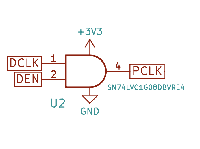
Nope. It will work but not the way i need. The PCKL need to be stopped for a moment to perform latching sequence. DEN will be inactive for the time where no pixels are pushed out.
Overall i can use logic gate to control PCLK but still need color data bit. DEN signal is rather useless and can be assigned as general GPIO, not for the LED matrix.